What are the safety issues here?
You have several issues that worry me:
- your lack of experience with both electrical and steam boilers
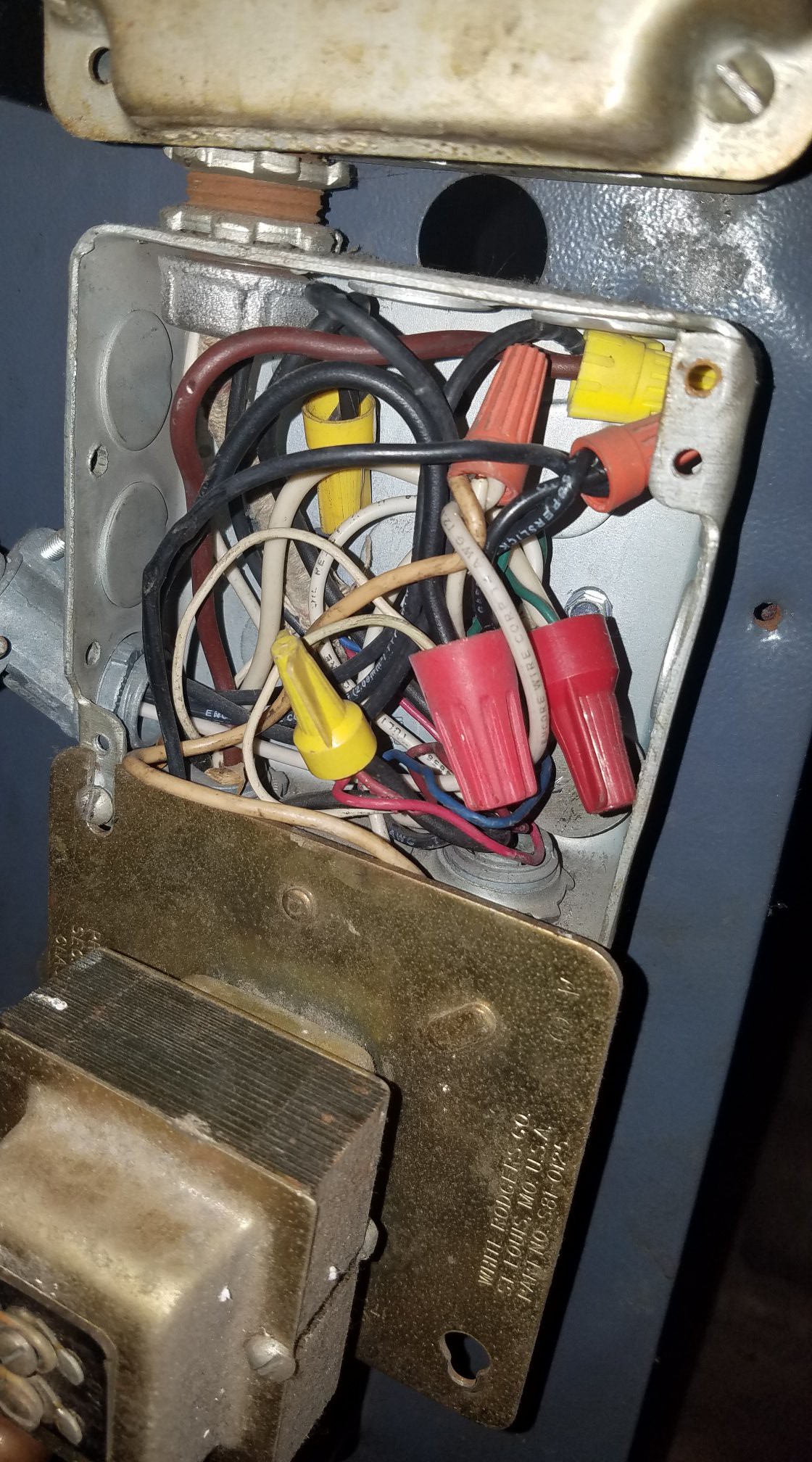
- the lack of a circuit diagram or a reasonable ability to create one from the spaghetti in that junction box. A link was provided in one of the comments but there is no certainty your system followed the diagram in that document.
- your boiler is wired terribly (see below) so the chances of your making a mistake are higher than they could or should be.
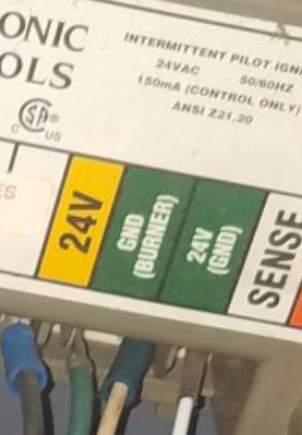
@ThreePhaseEel highlighted one big concern. Briefly: your thermostat is wired along with several safety devices any one of which can turn off the boiler. It is possible to wire the boiler so the thermostat alone can turn it on, bypassing the safety devices. That would be very bad.
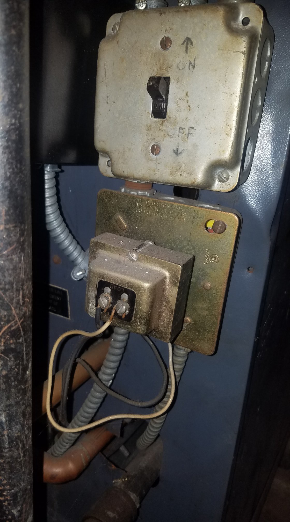
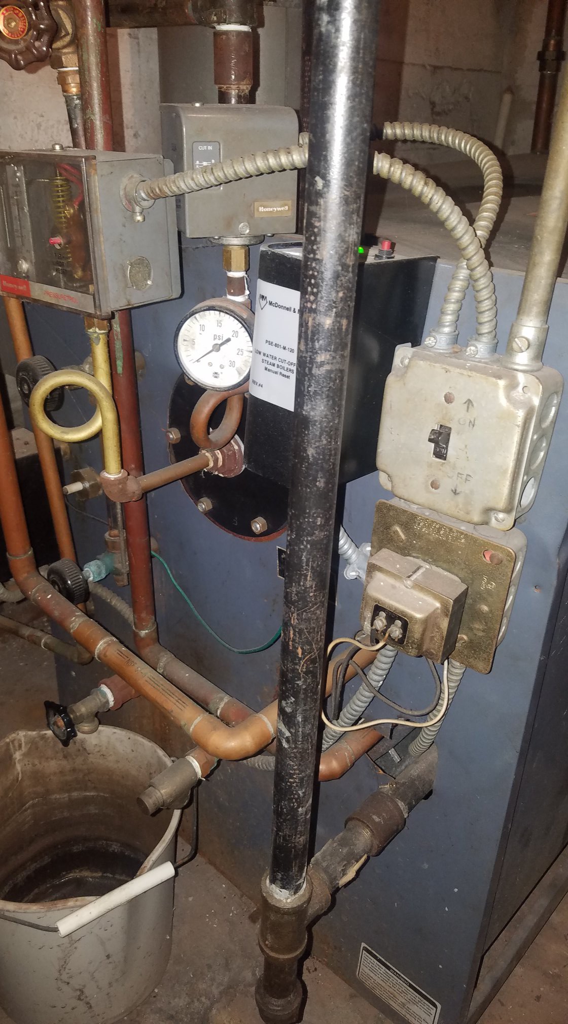
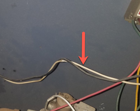
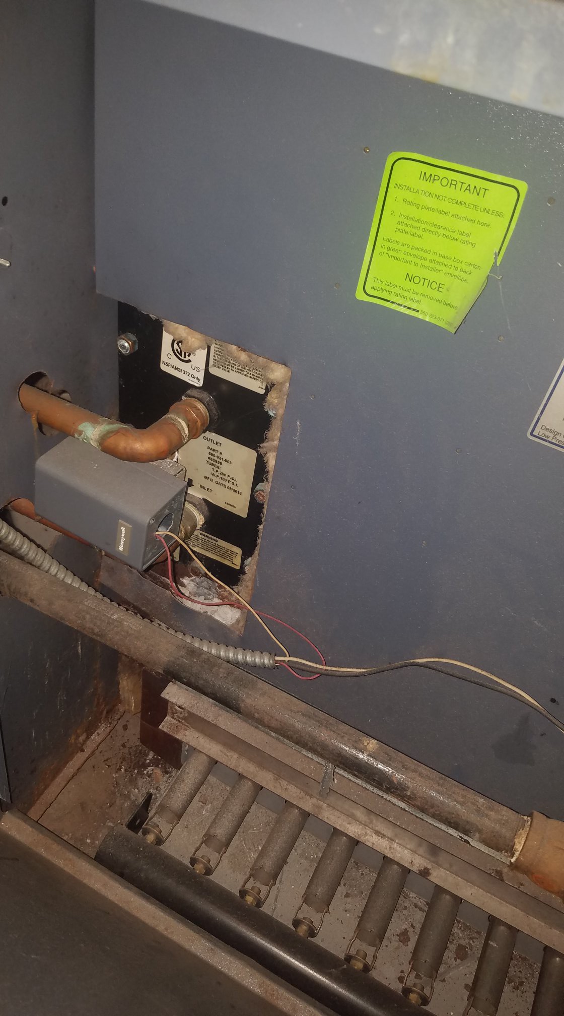
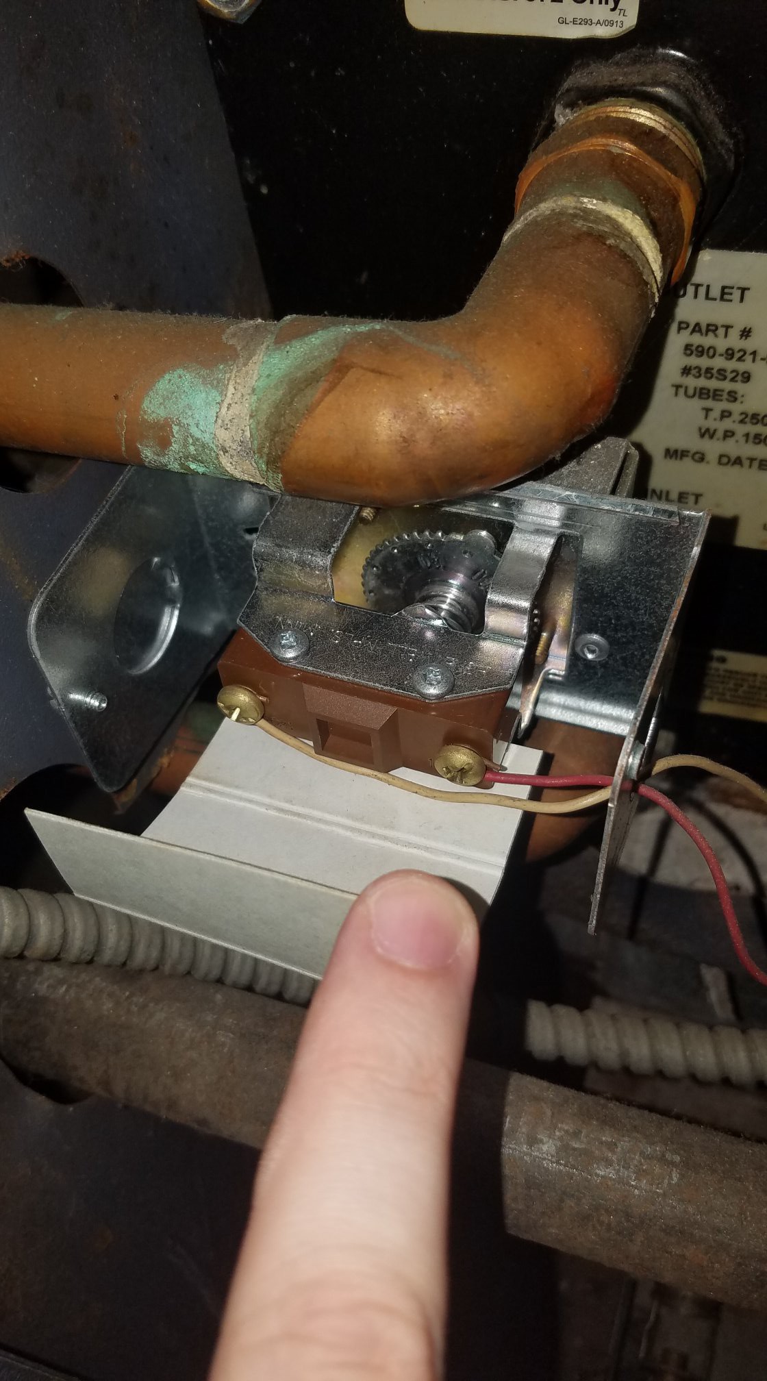
I’m highlighting a different safety issue: The purpose of that metal pipe (top right) and of the two metal boxes is to isolate and contain the high voltage wiring. The entire point of that metal plate that the transformer is mounted on is to provide and ensure that the high voltage wiring is on one side of the plate, inside the box, and the low voltage wiring is on the outside of the box. The thermostat wiring should be outside that conduit. The thermostat wire can be cable-tied to the outside of the conduit if it happens to be heading in the same direction.
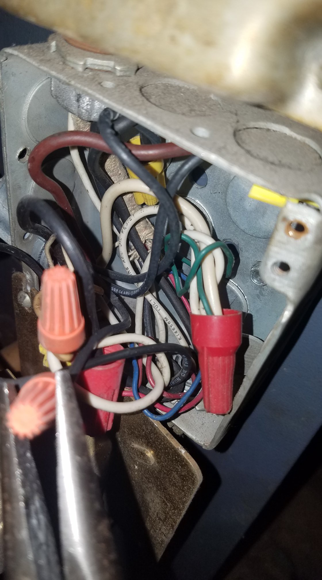
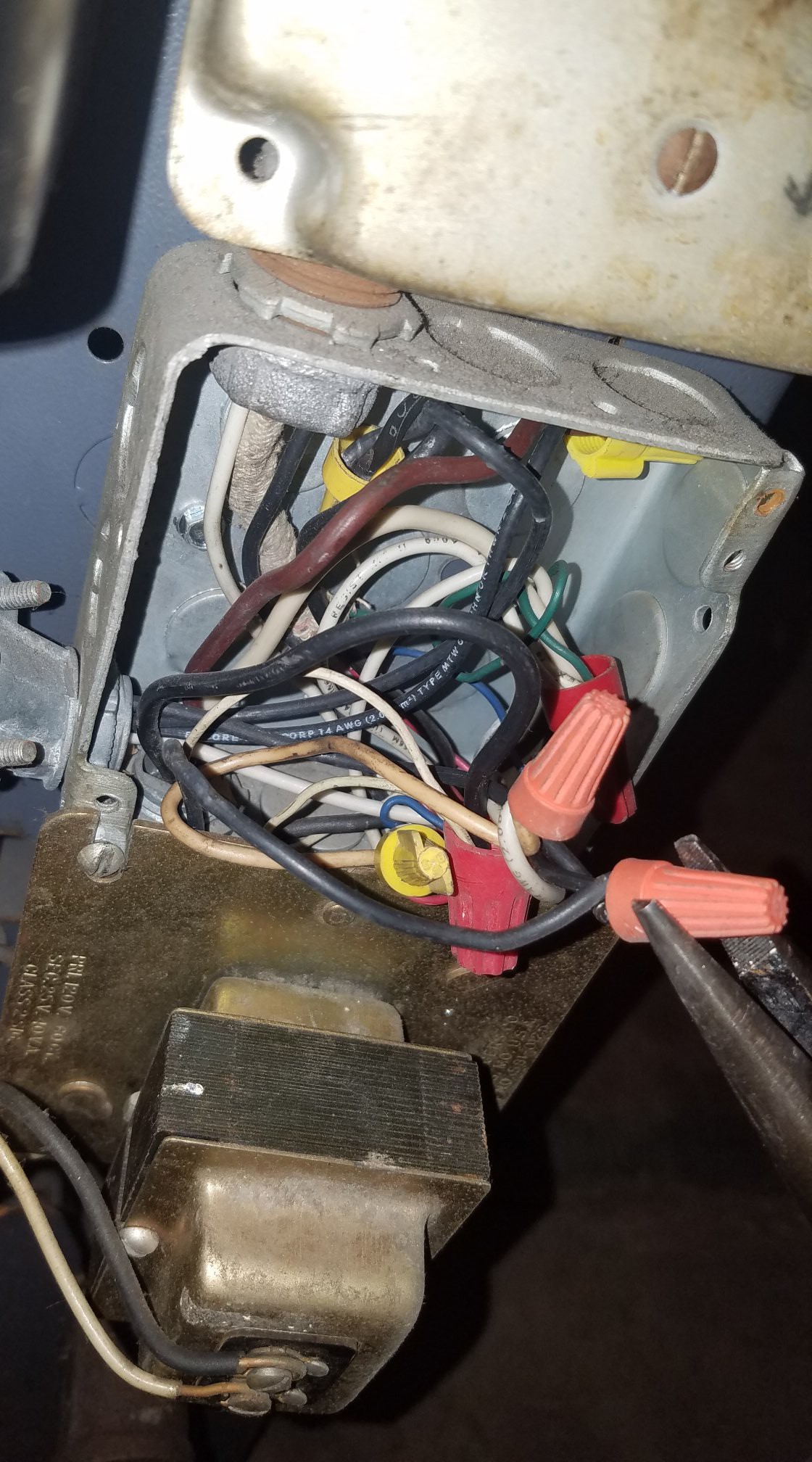
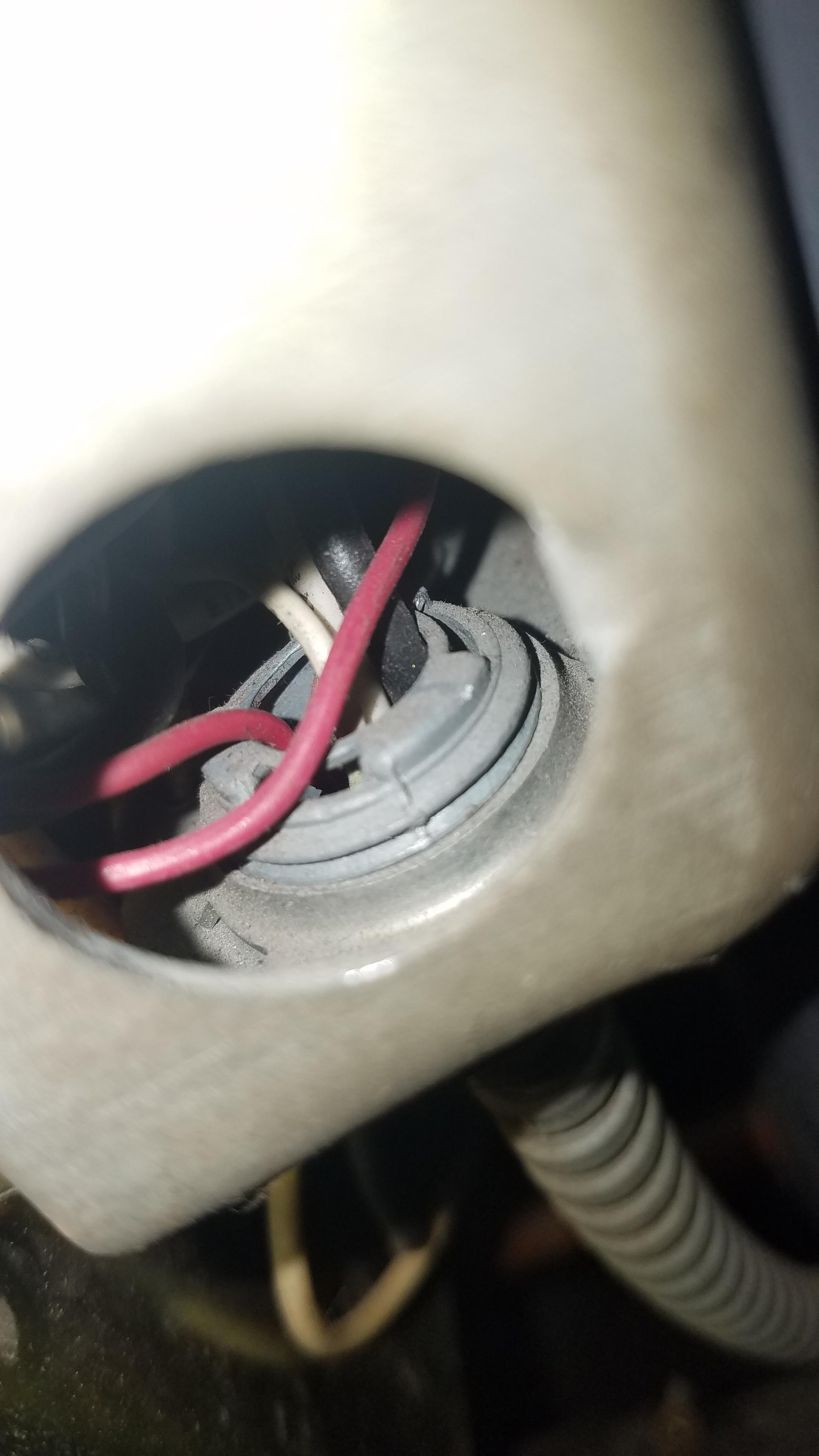
What you have is the low voltage wiring from the transformer wrapped around the edge of the metal plate, wedged between the plate and the sharp edge of the box and re-entering the very box that is literally designed keep it out. You have the thermostat running through the conduit with high voltage wiring, then you have all the high and low voltage wires mixed up in a spaghetti junction inside the box.
The main dangers are:
- Difficult to inspect and maintain correct wiring and function of the safety devices
- Faults or errors in wiring can cause high voltage to be applied to your low-voltage devices including the thermostat. That could start a fire and/or shock people who come in contact.
- Unintentional wiring errors such as installing a new thermostat could bypass safety controls. It's almost impossible with this mess to see, understand, or attempt to do things correctly.
I strongly suggest you have all this corrected by someone who is knowledgeable and who has some pride in their work. I'm pretty sure you can easily provide a C wire to your new thermostat, in fact I think it may already have on in the green wire but don't make any changes without cleaning this up.
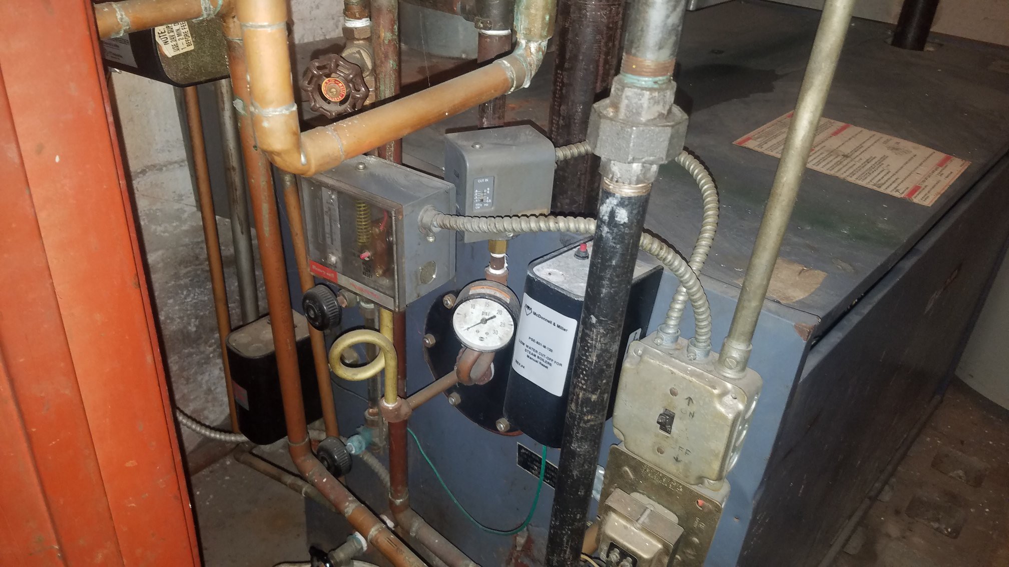
 This is behind the previous images Honeywell box (Aquastat?)
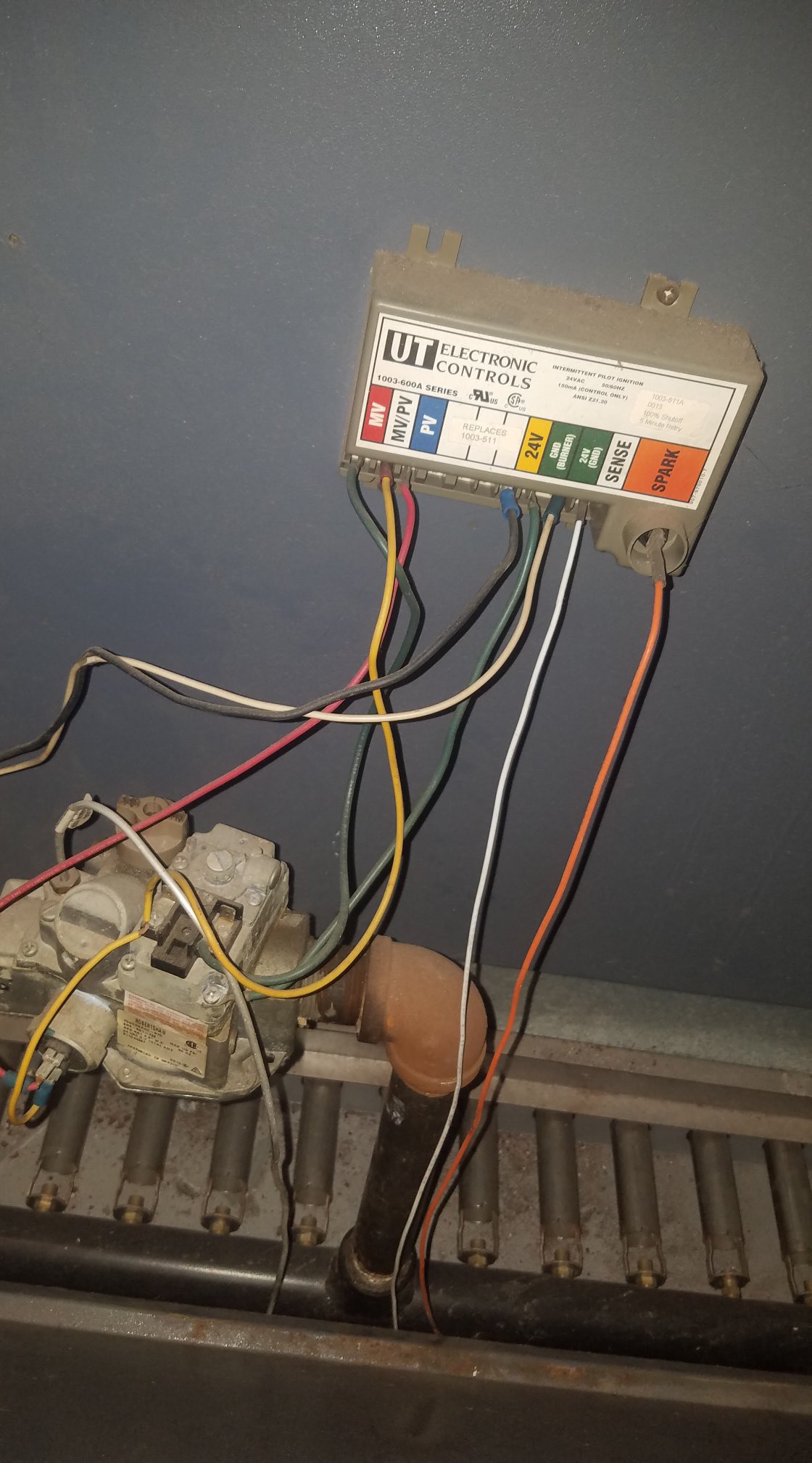
 this is the transformer?