5

I'm trying to replace 2 sets of three way switches with smart switches.

One end of each set requires neutral, and unfortunately there doesn't seem to be a straight forward way to accomplish that with my wiring.

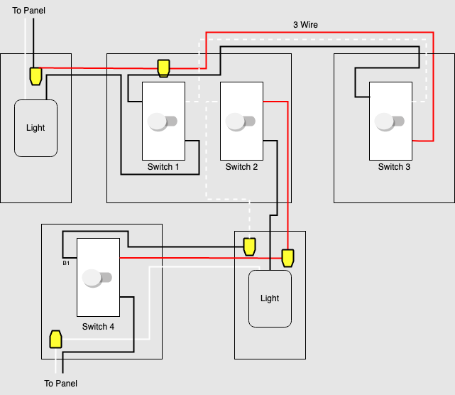
I've put together a diagram showing the wiring that I'm hoping will be helpful. This is my best understanding of what's going on but there may be mistakes so let me know if anything looks off.

My question is, is there anyway to get the neutral wire I need for both sets of switches? Both lights are on the same circuit if that helps.

Failing that, is there a setup that could allow me to replace one or both of these sets with single pole switches instead?

wiring diagram

kfoley
  • 153
  • 4

1 Answers1

7

Switch 1-3 are part of an old fashioned switch loop.

enter image description here

Switch 2-4 is a "lamp in the middle" sort of deal.

enter image description here

How to do it, though.

Things are made more difficult by the system being powered from 2 different power sources. By sheer luck, one of them can feed the whole shebang. Not the switch loop. That gets deleted altogether (capped off).

Now we have

enter image description here

Sorry for the bad photoshop, its line tool suddenly started painting random colors instead of the foreground color I selected.

The top left power feed is GONE. I recolored the top left cable from black-white to red-white. Colored electrical tape is amazing!

In all cases, black=always-hot, white=neutral, and red=switched-hot.

Switch 1 and 4 are smart switch "masters" for their respective lamp. Switches 2 and 3 are smart switch "remotes".

Note that the 1-3 pair have the red wire available for inter-switch signaling if they need it. However switch 2-4 does not, and it MUST be a type such as Insteon that uses wireless or powerline signaling for the remote to talk to the master.

Harper - Reinstate Monica
  • 313,471
  • 28
  • 298
  • 772