8

WARNING TO ANYONE READING THIS POST. DO NOT TRY WHAT I WAS PROPOSING AS YOU WILL GET SHOCKED AND KILLED OR YOU WILL BURN DOWN YOUR HOUSE AND BE KILLED.

Is it possible to add indicator lights to a hot water heater to indicate when an element is out? I have searched on the internet and I can't find any related information.

Thank you in advance for any help, Yeto

hot water heater wiring diagram

enter image description here

Would something like this work? The wires from the main panel are connected to the top of the hot water heater and they are already separated approx 6 inches. It would be very easy to clamp around any one of the wires without disconnecting or touching them. Would something like this be the best way to go. I basically just want to turn on the hot water and let it run until the thermostat kicks on the top element and make sure it is pulling approx 18 amps and then when the top clicks off and the bottom kicks on make sure the water heater is still pulling 18 amps.

https://www.aliexpress.us/item/2251832712380385.html?spm=a2g0o.productlist.main.5.1b9678a2ur4ZBn&algo_pvid=6682e15b-b47f-4d9a-8f72-d41cdc57bde7&algo_exp_id=6682e15b-b47f-4d9a-8f72-d41cdc57bde7-2&pdp_ext_f=%7B%22sku_id%22%3A%2266804801259%22%7D&pdp_npi=2%40dis%21USD%2116.22%2111.19%21%21%21%21%21%40211beca116714119047254008d0760%2166804801259%21sea&curPageLogUid=ssyKurB9sY0v

These indicator LEDs should be able to handle voltage without adding a resistor. (I am not going this route as I see now what I was proposing will not be safe. See warning at top.)

https://www.aliexpress.us/item/3256802692000480.html?spm=a2g0o.productlist.main.3.3b5e537cqShRcp&algo_pvid=afac6294-f269-4d2e-9fcf-db66fe20d0a7&algo_exp_id=afac6294-f269-4d2e-9fcf-db66fe20d0a7-1&pdp_ext_f=%7B%22sku_id%22%3A%2212000022591722893%22%7D&pdp_npi=2%40dis%21USD%211.38%210.69%21%21%21%21%21%4021021aa216714658984056757d0773%2112000022591722893%21sea&curPageLogUid=rLF0OYriQMWS

UPDATE

I did it. Found amp probe indicators on Amazon. Work great.

Have pics but don't see where I can add.

Michael Karas
  • 67,833
  • 7
  • 68
  • 153
Yeto
  • 81
  • 1
  • 3

3 Answers3

10

You're making this way harder than it is.

AC electrical wires throw a considerable magnetic field

in proportion to the current on the wire.

And there's no particular need to detect the amount of current on the wire - 10A vs 20A vs 30A - because resistive heating elements only draw current at one of three rates:

  • 0A
  • design A
  • infinity A, however this does not need to be disambiguated; the circuit breaker will trip and change this to a 0A reading.

Thus we are down to "current or not" as the only thing we need to detect. That's pretty easy. We can do that with magnetic reed switches, or better, Hall Effect sensors.

It simply boils down to finding the right physical places to surveil the wires.

enter image description here

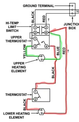
Anywhere along the green for the upper element. Anywhere along the red for the lower element.

Anytime you're trying to sense current, you must remember the golden rule of AC mains wiring: NEC 300.3 all related wires must be kept together in the same cable or conduit, so that currents are equal/opposite in any group of wires, and thus, the magnetic fields thrown by those wires cancel each other out. That is how we avoid eddy current heating, disturbing animals and attuned people, vibration leading to metal fatigue, and other harms. However, if we are trying to detect current, this rule is our enemy.

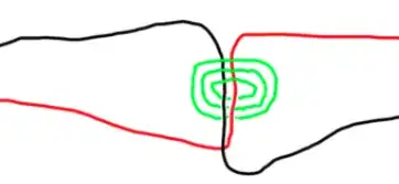
So we must carefully choose locations where the wire under observation is not next to other wires. Or alternately, twist them like this so the magnetic fields stack.

enter image description here

Do not intermix AC mains and low voltage wires

A cardinal rule of AC wiring is that you do not put conductive low voltage wires inside the same enclosure with AC mains wires, and then, have low voltage wires leave the enclosure and go somewhere not protected as well as AC mains wires. So with low voltage you have to create an optical or radio isolation - either keep ALL the low voltage stuff inside the enclosure including its power supply, or keep it all outside the enclosure and use magnetic fields, radio or optics to communicate through the membrane.

Water heaters typically have several access covers. If it were me, I would play with positioning the relevant wires against the access covers to see if the magnetic field will punch through the metal enough to be detected by a Hall Effect sensor (a reed switch is probably too much to hope for lol). Then your installation is neat as a button: all the low voltage DC stuff is on the outside of the steel enclosure and you have achieved separation. Otherwise you might put standard 1/2" knockout holes in the enclosure and filling them with approved plastic knockout covers (generally intended for a Romex cable, but I won't tell lol). One thing or the other should do the trick.

Then it's just Arduinos and Hall Effect sensors, straightforward stuff, the folks over on electronics.se can help with implementation when you get stuck. It's up to you whether to stick a WiFi shield on the Arduino so it can send you email lol.

You may notice that knowing "when the element is on" is slightly different than knowing "when it is supposed to be on". I think you can handle that in software. Just keep track of the last time the element has been seen in use, and alarm if it's been too long.

Harper - Reinstate Monica
  • 313,471
  • 28
  • 298
  • 772
4

In the configurations you have drawn, the LEDs will not show if the element has burned out.

The top LED between the thermostat terminal two and the top terminal in the lower element is in parallel with the piece of wire labeled "black" (very low resistance and practically 0 voltage across the wire), so that LED will never light.

The bottom LED is across thermostat terminal two and the bottom terminal in the lower element. It is in parallel with the element, receiving all the voltage coming from the thermostat. It will be lit all the time the thermostat is on, even if the element has burned out. It is wired parallel, just like house wiring, where one light can be off and another on independently.

Additionally, using LEDs alone for this will let the "magic smoke" out of the LED, because 240V AC is staggeringly too much for an LED, which may need 1.5-2 V DC with a current limiting resistor (look on the Electronics Engineering Stack exchange about running LEDs).

You need to read the current going through the wire labeled "black" to determine if the element is running. When the element burns out the current will stop flowing. The safe way to do this is with a clamp ammeter or a current clamp sensor over the "black" wire, along with a sending device that can signal when the current drops below a determined value or to zero. Do a web-search about current sensors for house-voltage-level electricity.

You can put such a sensor on the "yellow" wire also, to sense the top element status.

Triplefault
  • 13,096
  • 1
  • 21
  • 52
1

This can vary depending if you want the light to stay on once a fault as been detected or only while there is a fault. You can build a circuit that detects when the power is turned on to the element or use that to power your circuit. Then if it is not drawing a minimum amount current you light your indicator. This can also be accomplished with a small computer such as an Arduino or Pi. There are many examples of this online. My recommendation is the simplest, purchase and install a current sensor relay.

Gil
  • 7,112
  • 1
  • 7
  • 21