It's best to avoid touching the trusses if possible, so reinforcing the existing truss is probably a bad idea. For 2 plies of Spruce-Pine-Fir #2 2x6s spanning wall to wall, the capacity is 770# (for 2 plies of Spruce-Pine-Fir #2 2x4s, the capacity is 250# based on deflection and 350# based on strength, where exceeding deflection constraints is associated with superficial damage like cracked drywall).
The 2x6s need to be fastened together along their whole length. Face nail along both edges with 16d box nails on 12" centers or 16d common nails on 16" centers (see item 10 in Table R602.3(1) under IRC R602.3). The ends each get 3 toe nailed 10d box nails like a normal joist (see items 2 and 22 in Table R602.3(1) under IRC R602.3). The 2 plies of 2x6 are sufficiently stocky that you don't need to worry about bracing them against rotation at the ends or anywhere along the span (see 4.4.1.2(a) from Chapter 4 of the NDS).
Analysis
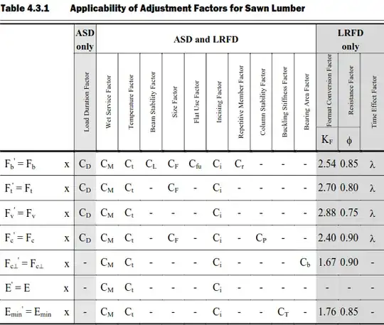
Given a lumber grade and species like #2 Spruce-Pine-Fir, material properties like modulus of rupture (Fb) or elasic modulus (E) need adjustment based on section geometry, ambient moisture conditions, etc. before these properties can be used in design equations.
Chapter 4 of the NDS Supplement provides the unadjusted values, in this case Fb = 875 psi and E = 1400000 psi. Following Table 4.3.1 from Chapter 4 of the NDS (shown below), the adjusted values are Fb' = Fb·CF = (875psi)(1.3) = 1140 psi and E' = E = 1400000 psi. The 2 plies of 2x6 allow a beam stability factor (CL) of 1.0 thanks to the stockiness of the 2 plies of 2x6 lumber. A skinnier beam like a single 2x10 is vulnerable to lateral torsional buckling and would require a strength reducing beam stability factor. (Kind of. The load applied from the underside technically stabilizes such a beam, but one look at the thing would convince you that it still needed bracing.) If you're curious about the various adjustment factors, then see 4.3 from Chapter 4 of the NDS.
Deflection
IRC R301.7 prescribes a maximum live load deflection of L/240 for drywall ceilings, Δ ≤ L/240.
For the point load located 25" from a support, I use the beam deflection tables from the AISC Manual of Steel Construction:
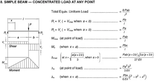
Taking a = 162" - 25" = 137" and b = 25", the 770# capacity value and E' = 1400000 psi from the analysis preliminaries yields
Δ = (770#)(137")(25")(137"+2·25")[3·137"(137"+2·25")]1/2/[27·(1400000psi)(1/12)(3")(5.5")3(162")] = 0.54".
This deflection satisfies the Δ ≤ L/240 = 162"/240 = 0.68" requirement.
Bending
3.3.1 from Chapter 3 of the NDS constrains bending stress with the "adjusted bending design value," Fb' from the analysis preliminaries.
From mechanics of materials (Bernoulli beam theory), the maximum stress in a bending section follows from its maximum bending moment Mmax and elastic section modulus S as fb = Mmax/S. Mmax for the self weight occurs at the beam's midspan. Mmax for the point load occurs at the point load. Adding these two values will generally provide an upper bound on the Mmax, but not Mmax itself. In this case, however, the self weight's contribution is so small that I use the upper bound instead of deriving the exact Mmax.
The table entry from the Manual of Steel Construction above provides the maximum bending moment due to the 770# capacity load and the well known wL2/8 provides the maximum bending moment due to self weight. Adding the two yields
Mmax = (770#)(25")(162"-25")/(162") + (0.5)(62.4#/ft3)(1ft/12")3(3")(5.5")(162")2/8 = 17200 #-in,
where I've used a 0.5 specific gravity for the softwood so that its product with water's density provides a softwood density. Dividing this result by the elastic section modulus provides fb = (17200#-in)/[(1/6)(3")(5.5")2] = 1140 psi. This fb is equal to Fb' from the analysis preliminaries by construction.


