5

I recently replaced my kitchen island, and found out that I have some MWBC in my home. I figured it out and the new receptacles are working.


On a separate line, at the countertop, I went to replace a working old dirty receptacle with a GFCI receptacle. Now the GFCI trips. This is how it was originally wired (and working w/ the old non-GFCI outlet)

The MWBC comes in and gets split to items in the 2 gang box 1.[black] a GFCI (which feeds another outlet further down) 2. [red] a 3 way switch (which feeds another light fixture further down)

Diagram

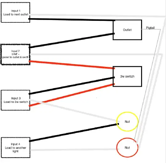
My thoughts: A. The "Input 1" neutral should connect to the outlet, not the wire nut, right? B. The yellow nut is something I can't figure out.

This is what I tried doing, but now the breaker trips. I know one thing I got wrong/ didn't consider on my attempt to rewire is how will "Input 4 / load to another light" work- it seems like it would always be one.

Diagram

Michael Karas
  • 67,833
  • 7
  • 68
  • 153
user241867
  • 51
  • 1

2 Answers2

4

GFCIs have the ability to provide downline protection to other outlets. This is the ONLY legitimate use of the "Load" terminals. The "Line" terminals support 2 wires per screw, see instructions for how. If you are not intent and competent to provide downline protection for onward devices, then don't use Load and put everything on Line.

OK, so "input 1” carries power onward to another receptacle, am I correct? Alright, make a decision whether you want that receptacle there to be protected by this GFCI here. The main benefit of doing so is being able to use a $3 socket instead of a $16 GFCI socket.

If you do, then put both its hot and neutral on the GFCI Load terminals. Remember to use the "GFCI Protected" stickers, or the inspector will tag em for not being GFCI.

If you don't, then leave its neutral in the bundle and move its hot to GFCI Line using the aforementioned 2-wire trick.

Also, if you have colored electrical tape not black red green or white, it helps understanding the circuit to make both travelers the same oddball color. They are interchangeable and there is no need to distinguish them from each other. I like yellow, because, brass screws.

Oh, one more thing on the 3-way. You appear to be using the white wire as the switched-hot. That is the one wire it CAN'T be. Your order of precedence is neutral > always-hot > anything but switched-hot. So in this case you would use it as a traveler.

You do need to mark the white wire black or a color, so hey, back to what I said about make both travelers an oddball color.

Harper - Reinstate Monica
  • 313,471
  • 28
  • 298
  • 772
3

The "Input 1" neutral should connect to the outlet, not the wire nut, right?

Yes. Just be careful about NEC 300.13(B). By direct connection of the neutral wire, you can no longer mix and match the red and black wires of the MWBC. You will be treating the receptacle and anything past it as a single circuit. This will be necessary to install the GFCI anyway.

This is what I tried doing, but now the breaker trips.

Now you've connected the 3-way switch loop to the neutral wire nut. That's a short circuit, and you're lucky the breaker did its job. Put it back the way it was before you broke it.

By the way, this is why NEC 200.7(C) forbids using white wires as return-from-switch conductors. Neither diagram is correct in that sense. The white wire must be "reidentified" and must be used as a traveller in this scenario. This assumes cables instead of conduit, and would also explain the confusion with the yellow wire nut.

Robert Chapin
  • 8,102
  • 1
  • 15
  • 37