2

When talking about neutral faults in this answer, I (incorrectly) said that a neutral fault could lead to a shock hazard. It was pointed out in the comments that I was dead wrong, and that the scenario that I presented was incorrect.

I looked at the problem for a bit, but just couldn't wrap my head around it. So I came up with a circuit diagram, and posed a question in chat.

The problem

So given this diagram, will R2 light up?

Tester101
  • 133,087
  • 80
  • 327
  • 617

3 Answers3

4

As it turns out, no. R2 will not light up.

The Experiment

Being true to my username, I decided to test this out. No, I didn't grab hold of a grounded (neutral) conductor (Sorry to disappoint those of you who would have liked to see me get zapped into oblivion).

I started by wiring up a sample circuit.

The circuit

Then I added an extension cord, so I could plug it into a receptacle.

The circuit with extension cord

When I flipped the switch, the second light did not light!

The circuit energized

Finally I took some readings with my ammeter, and this is what I found.

The circuit measurements

Notes:
I ended up using 15W compact flourescent lamps instead of 60W incandescents, which is why I measured only 0.125A.

The Explanation

Kirchhoff's second law says that the total voltage applied to any closed circuit path, is always equal to the sum of the voltage drops in that path.

If you look at the circuit, there is a "closed circuit path" which I've highlighted in red below.

Highlighted Circuit

If we apply 120 volts to the loop, the total voltage drop in the loop will also be 120 volts. However, the majority of the voltage drop occurs in the first part of the loop (the wire to the switch, the switch, the wire between the switch and light, the light, and the wire from the light to the first twist-on wire connector). From this point, the same voltage will be applied to the remainder of the first loop as is applied to the second loop. This voltage will be so small, it will not be enough to light the bulb.

Maths

Each length of wire in the photo is 14 AWG, and 6" long. We can determine the resistance of each bit of wire using Table 8, from chapter 9 of the National Electrical Code. Solid, 14 AWG, uncoated, copper wire has a resistance of 3.07 ohms per 1000 feet.
3.07 ohms per kFT. / 1000 FT. = 0.00307 ohms per foot
0.00307 / 2 = 0.001535 ohms per half foot (6")

We can determine the resistance of a 15W compact fluorescent lamp (CFL), using Ohm's law Resistance (R) equals voltage (E) squared divided by power (P).
R = 120V ^2 / 15W = 14400V / 15W = 960 ohms

If we plug those values into a diagram, we'll end up with something like this...

Diagram with resistors for everything

Now we can determine the total resistance in the circuit (we'll assume 0 ohms in the switch for simplicity).

Ra = R1 + R2 + R3 + R4 + R5 + R6 = 960.007675 ohms
Rb = R7 + R8 + R9 = 960.00307 ohms
Rt = (Ra * Rb) / (Ra + Rb) = 921610.31522356225 / 1920.010745 = 480.0026862472388142806982051551

Next we'll calculate the total current.

Ia = Et / Ra = 120V / 960.007675 ohms = 0.12499900065903118951627131522672 amperes
Ib = Et / Rb = 120V / 960.00307 ohms = 0.12499960026169499645454258807735 amperes
It = Ia + Ib = 0.12499900065903118951627131522672 amperes + 0.12499960026169499645454258807735 amperes = 0.24999860092072618597081390330407 amperes

Then we can calculate the voltage drop across each component.

DeltaR1 = R1 * Ia = 0.00019187346601161287590747646887302 volts
DeltaR2 = R2 * Ia = 0.00019187346601161287590747646887302 volts
DeltaR3 = R3 * Ia = 119.99904063266994193562046261765 volts
DeltaR4 = R4 * Ia = 0.00019187346601161287590747646887302 volts
Total Voltage Drop after R4 = DeltaR1 + DeltaR2 + DeltaR3 + DeltaR4 = 119.99961625306797677424818504706 volts

Voltage after R4 = 120V - 119.99961625306797677424818504706V = 0.00038374693202322575181495294V


NOTE: While looking at the diagrams, it may seem as though you're dealing with a simple parallel circuit. However, it's actually a short-circuited series circuit. This is why the results may be counter intuitive, and confusing.

Tester101
  • 133,087
  • 80
  • 327
  • 617
2

Alright, there seems to be a lot of confusion about this, so allow me to give a quick overview of the first week or two of a physics course on electricity.

Analyzing circuits in general is pretty complicated; even a simple circuit with just a resistor, inductor, and capactitor takes about a semester to fully understand. However, most home circuits can be modeled using just resistors, which makes them much, much easier to understand.

I'm going to assume you're familiar with the electrical concepts common for home-wiring: current (amperage), voltage, alternating current, etc.


This is what a typical circuit diagram looks like:

Typical circuit

Let's first review what all these symbols mean.

generator
This symbol is an AC (alternating current) generator, the kind of power supplied to homes. It would be equivalent to the left- and right-prongs in an outlet.

resistor
This is the symbol for a resistor, something which resists the flow of current. It can be used to model a lightbulb, a person touching a wire, or even the resistance of the wire.

wire
This is the wire. We assume it has 0 resistance; if we need to model the resistance of the wire, we add an imaginary resistor to the circuit.

Note that the voltage across any two points on our ideal resistanceless wires will always be 0, seeming to indicate (by Ohm's Law, below) that there can never be any current across them (or rather, the current is 0/0). We ignore this fact as theoretical, since real wires will always have some resistance.

ground
This symbol is called "ground," but it actually represents the neutral wire, not the third prong that an electrician would call "ground." If there is more than one ground in a circuit diagram, we assume they are all connected.


Analyzing these kinds of circuits only requires knowledge of three laws: Ohm's Law, Kirchoff's Current Law, and Kirchoff's Voltage Law.

Ohm's Law

Voltage = Current * Resistance
(aka. V = IR)

Thus, if you only know two of (Voltage, Current, Resistance) for a single resistor, you can find the third.

Kirchoff's Current Law (KCL)

"The total current entering a wire-junction or device is equal to the total current leaving the junction/device"

If you think about the water-analogy of electricity and replace "current" with "water," this seems almost obvious. You could also call this "conservation of current."

Note that this means that current is not "used up" as many people seem to believe.

Kirchoff's Voltage Law (KVL)

"The sum of all voltages in a loop is 0"

This sounds complicated, but it's also really simple; it basically says that, if you sum all the voltage-increases and voltage-decreases in a loop, then when you get back to where you started you get 0. If you replace "voltage" with "pressure," this also makes sense with the water analogy.

KVL
(image taken from here)


Finally, let's analyze your circuit.

your diagram

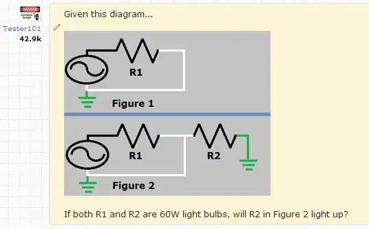
By KVL, the voltage across R2 = 0. By Ohm's law, this means the current through R2 = 0, so the light will not light. The diagram you gave in an answer...

your other diagram

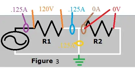
is exactly correct, assuming R1 = 960Ω (the resistance of R2 is irrelevant).


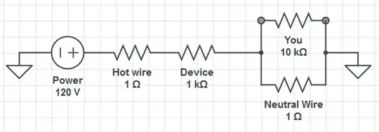
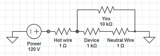
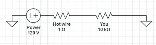
There was concern in the comments above that this circuit isn't realistic, since it doesn't model the resistance of the wire. This is true; let's try analyzing a more realistic circuit.

Typical circuit

What is the current through "You" in this circuit?

First, we find the current through the entire circuit. This can be done using only the three above laws and a lot of algebra (Physics students are taught a shortcut called equivalent resistance). Since this isn't an algebra class, I'll skip this step and just tell you the equivalent resistance is just slightly under 1002Ω, meaning the current drawn from the generator is about 120V/1002Ω ≈ 0.11976A (you are welcome to do the calculations yourself, however).

By KCL, we see that

(Current through generator)
= (Current through hot wire)
= (Current through device)
= (Current through You + Current through neutral wire)
= 0.11976A

Using Ohm's Law, that means the voltage DROP across the hot wire is

1Ω * 0.11976A = 0.11976V

and the voltage DROP across the device is

1000Ω * 0.11976A = 119.76V

Since the voltage INCREASE across our AC generator is 120V, by KVL this means that the voltage DROP across You (and across the neutral wire) is

120V - 119.76V - 0.11976V ≈ 0.12V

Finally, by Ohm's Law, this means the current across you will be about

0.12V/10kΩ = 0.012mA

If "You" in that diagram is actually you: according to this answer, the threshold for sensation of 60Hz AC is around 0.4mA. So although current would indeed flow through your body, you wouldn't feel it, even if you were standing in a tub of water.

In the case where "You" is actually an incandescent lightbulb, current will flow, but the light it produces will likely be so dim that you can't see it.

And if "You" is a florescent lightbulb like in your pictures, the ballast will prevent any current from flowing at all.


Finally, let's compare the above case to one where you touch the hot wire while the device is on and you are grounded:

device is on, touch hot wire

Or the similar case where the device is off (or the neutral becomes disconnected!):

device is off, touch hot wire

In both cases, the current through you would be just slightly less than 12mA. 12mA is enough to cause severe pain and contract your muscles so you couldn't let go of the wire. And if you're sweaty or have lower skin resistance that day, the current would be even greater, possibly enough to kill you (which would require around 100mA, according to the above link).

1

That is an idealized model of household wiring.

You are modeling all of your wires as if they are perfect conductors.
All wires (excluding superconductors) have a resistance to them.
There may also be some added resistance at every point that a wire joins up with another. ( wire nuts, outlets, etc )

You also failed to take into consideration that the wires are adjacent for a significant distance.
So they also act a bit like RF transmission lines, inducing current into ground wire as well.

All of this adds up to the voltage at an outlet for all of the three wires being different than at the breaker box.


Here is an easy way to prove it.

  1. Take a good multimeter, ( 1 MegOhm or more impedance ) set it to AC volts ( 20 VAC setting should be good ).
  2. Touch one of the probes with your fingers. ( don't touch anything else )
  3. Place the other probe in contact with the neutral and ground in turn, at the end of a heavily loaded circuit. Note the readings.
  4. Repeat at an outlet near the service entrance.

I get 5 VAC on the neutral, and 0.7 VAC on the ground of a highly loaded circuit.

On an outlet near the service entrance, without a load, both the neutral and ground have about 0.15 VAC.

I also went and measured the voltage from the grounding rod, to a point in the ground a few feet away and got that same 0.15 VAC measurement.

To prove that the multimeter was functioning correctly, I touched both probes with my fingers, and got 0 VAC.


So not only can you get a shock from the neutral wire, you can also get one from the ground wire as well.
For example sitting on the edge of a pool with a grounded pump, and a perimeter that is not grounded to the same potential.

I'm fairly sure I did this test before, and got higher readings on the grounding rod. They have put in some new transmission lines, and poles for a new substation; which may have helped pull the ground conductor closer to 0 VAC.

That's also assuming that a homeowner didn't replace an outlet and mistakenly swapped the hot for the neutral.

Brad Gilbert
  • 551
  • 4
  • 9