1

I have a brand new Square D sub-panel installed in my barn that replaced an old panel that had been there for many years and was deemed a fire hazard by the inspector. The new panel has a grounding wire that runs from the panel grounding bar to outside and is connected to a copper rod sunk 6 ft into the ground. For the receptacles on the ground floor I have a 20 AMP GFCI breaker installed in the panel that feeds a single line that they are daisy chained to. The breaker is wired correctly (hot wire to breaker as normal, neutral wire to the breaker neutral and then neutral pig tail from breaker to the neutral bar on the panel. Ground as normal goes to the ground bar on the panel).

When I plug in my outlet tester it reads "Bad Ground" on any receptacle I plug it into in the barn. I tested the same unit in my house and it reads green (all correct). Here's what I've tested so far with my multimeter:

  • continuity between receptacle ground pin and ground screw - good
  • continuity between receptacle ground pin and ground wire that comes from panel - good
  • continuity between ground bar on panel and the other end of the ground wire that connects to the grounding rod - good

What could be going on giving me this reading?

RedGrittyBrick
  • 24,700
  • 12
  • 50
  • 94
snappymcsnap
  • 111
  • 1
  • 2

3 Answers3

2

If you only have a three wire feed to the barn then the panel should have the neutral and ground connected together.

The old method of wiring a sub-panel in a separate building was the 3-wire method like you have. The wires should be Hot, Hot, Neutral not Hot, Neutral, Ground.

Consequently the sub-panel would have been bonded (neutral and ground connected together). So, the replacement panel should be bonded.

If you have not bonded the neutral to the ground in your barn that is why your tester is saying it has an open ground.

Here is the pertinant NEC section:

(B) Grounded Systems.

(1) Supplied by a Feeder or Branch Circuit. An equipment grounding conductor, as described in 2S0.118, shall be run with the supply conductors and be connected to the building or structure disconnecting means and to the grounding electrode(s). The equipment grounding conduc- tor shall be used for grounding or bonding of equipment, structures, or frames required to be grounded or bonded. The equipment grounding conductor shall be sized in ac- cordance with 2S0.122. Any installed grounded conductor shall not be connected to the equipment grounding conduc- tor or to the grounding electrode(s).

Exception No.1: For installations made in compliance with previous editions of this Code that permitted such connection, the grounded conductor run with the supply to the building or structure shall be permitted to serve as the ground-fault return path if all of the following requirements continue to be met:

(1) An equipment grounding conductor is not run with the supply to the building or structure.

(2) There are no continuous metallic paths bonded to the grounding system in each building or structure involved.

(3) Ground-fault protection of equiprnent has not been in- stalled on the supply side ofthefeeder(s).*

Good luck and stay safe!

ArchonOSX
  • 20,870
  • 3
  • 30
  • 53
1

Ground rods should be 8' if not certified 2 rods are normally required. This may be the reason for a bad ground indication.

Ed Beal
  • 103,727
  • 4
  • 79
  • 158
0

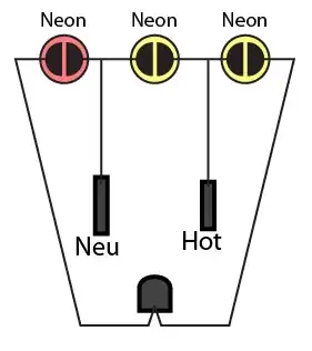
On those hokey outlet testers, the legends are about as useful as a "magic 8-ball". They are wild guesses as to the problem. That said, the simple ones are just this, which give you 3 neon lamp tests at once. On my simple one, I wrote NG, HN and GH under the lights, peeled off the legend, and suddenly it's a Really Useful Tool.

enter image description here

Yours, unfortunately, appears to have some added digital logic to wreck that simple functionality.

Here's your problem:

The new panel has a grounding wire that runs from the panel grounding bar to outside and is connected to a copper rod sunk 6 ft into the ground.

and fullstop. Let's review. Current travels in loops. Current doesn't want to get to ground, it wants to get to source. For hot, source is neutral. The grounding shield is still designed to return wayward hot to source, and it does that via the one neutral-ground bond in your main panel.

Of course for natural electricity, lightning and ESD, source really is ground.

The problem is, in your case, you've correctly separated neutral and ground in the subpanel, but your only connection between shed and house is a bunch of dirt. So I see four ways to fix this, worst to best:

Unhook the grounds

Currently your GFCIs are your only line of protection. The grounding system actually works against you, because if a machine has a ground fault, it's going to "light up" the entire grounding system and make it dangerous. Of course, the the GFCI's should prevent this.

Use the grandfathered method (if allowed)

Normally you separate neutral and ground in the subpanel. Under the method now illegal, which you may be grandfathered into, outbuildings could ignore this, bring over a combo neutral-ground, and tie neutral to ground in the subpanel. In this scenario, you would do exactly that.

Convert to 120V; re-task a Hot to be Ground

If you don't really, really need 240V out at the shed, you have the option to switch the service to 120V. You abandon a hot to free up the extra wire.

If one of your conductors is bare wire, or smaller than the others, it's probably now the neutral, and must become the ground. If one is green, it must be ground. Otherwise, pick any. It's important not to mix up neutral and ground, so I would make one change at a time in the main panel and measure how it affects the subpanel.

You will end with a subpanel where half the breaker positions don't work, typically every other row of spaces. Move your breakers to the live spaces, and you're done. If you need empty fillers, I just use $4 plain breakers. They're not much more than the hard-to-find blank covers, better built, and hey - you have spare breakers. Piece of red tape with N/C and you're all done.

Run a ground wire

The nuclear option here is to run a separate, physical ground wire. This does not need to use the same route as the conductors - for instance if it's possible to circumnavigate your driveway, you can do that. Your required size is smaller than #2 but must be copper unless you install it using a proper wiring method.

You do not need to tear out the existing 3-wire cable and replace it with 4-wire cable. That would be a silly waste of money.

Harper - Reinstate Monica
  • 313,471
  • 28
  • 298
  • 772