When I took my cylinder heads apart, I wasn't aware of the need to keep track of the order of valve lifters so I didn't. I did, however, separate the left from right side of the engine (V6 Tacoma). So I have two sets of 12 lifters each that I need to redistribute in their old/new places. Ideally, they would each go in the exact same old place it was before but I think that matters less considering that I lapped my valves, which would introduce irregularities so the gaps would vary, making it unlikely that the old order will now fit.
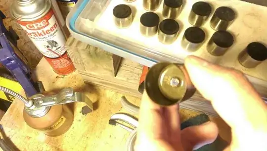
One thing that may be helpful is that each of my lifters has a size inscribed inside it (the one in the picture is 39, can't be seen very well).
Here is the distribution of sizes on the left side of my engine:
- 39 x 3
- 46 x 2
- 38 x 2
- 45 x 1
- 43 x 1
- 41 x 1
- 40 x 1
- 37 x 1
So I don't know where each one from before went nor have I been able to find a factory diagram on the interwebs. For the purposes of measuring the lash between the valve stem and the cam, I understand I need a lifter in place as a point of relative measurement for the sake of finding and being replaced by another lifter that ultimately fits the size. So, my question is, considering that I don't have the original order, how can I determine what a good initial distribution of these would be? Or does it matter because the lash is everywhere bigger than every one of these lifter sizes and I can just initially set them randomly?
I understand, according to my Haynes manual, the lifters have to be on the valves in some initial order and the camshafts and the timing chain need to be on. The manual says put piston 1 [I think the right side, the one closest to the front (radiator)] in TDC, then measure 8 specific valves (manual has a diagram which ones), then spin the crank 2/3 turn and do the same for another specific set of 8, then repeat one more time. I will also need to use a micrometer to remeasure the actual thickness of each lifter because it may have varied over time from what it says it is on it.